
What Tight-Tolerance CNC Machining Needs From Your CAD
A CNC quote that keeps moving is rarely the shop being difficult. It is almost always a CAD file that has not answered the questions a real tool path needs answered: which surfaces actually need tight tolerance, what the part looks like once it is re-engineered for machining instead of printing, and whether the geometry has been validated against a real cutting tool rather than just a screen render.
Machining-ready geometry is not the same as printable geometry
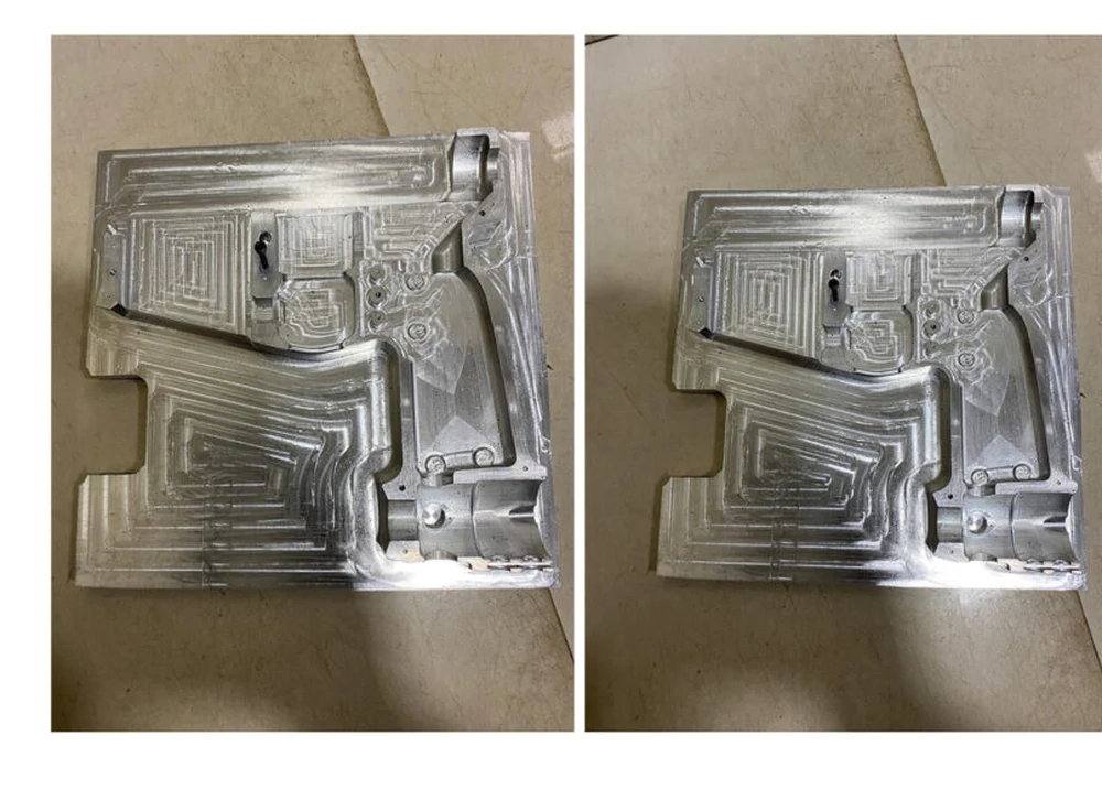
Our Airsoft Gun Housing project started life as a 3D-printed design and had to be re-engineered specifically for CNC requirements, ensuring proper tool paths, tolerances, and manufacturability in aluminum. A shape that prints fine layer by layer can be effectively unmachinable if it relies on internal geometry a cutting tool cannot reach, which is exactly the kind of detail a CAD file needs to resolve before it goes out for a quote.
Prototypes exist to validate tolerance and fit before the number locks in
That project machined several aluminum prototypes on a VMC specifically to validate precision, fitment, and performance under realistic handling conditions, alongside a structural weight-reduction pass and simplified assembly and disassembly design. Each of those changes reduces the tolerance and material questions a shop would otherwise have to ask, which is what keeps a quote stable instead of shifting after the fact.
What to check before sending a CAD file for a CNC quote
Flag which surfaces genuinely need tight tolerance versus which ones do not, confirm the geometry has been checked against real tool-path access rather than assumed, and resolve assembly and fitment questions before the file goes out. A CAD file that has already answered these gets a stable, accurate quote back. One that has not gets a list of questions, and a number that keeps changing until it does.