
What We’ve Learned Building PCB-Integrated Hardware, From Scoring Systems to Smart Pouches
Most product briefs that land on our desk describe a shape first and mention electronics second, as if the PCB is a component that gets slotted into a finished enclosure. In practice it almost never works that way. Once a product needs a battery, a display, or a sensor, the electronics stop being an ingredient and start setting the rules the mechanical design has to follow. A handful of real projects make the pattern easy to see.
When the electronics decide the housing, not the other way around
A water flosser project we took on started with reverse-engineering an existing product to understand how it worked, then rebuilding it with two features the original did not have: a heating element to warm the water, and a dual-liquid system so a user could run mouthwash and water from the same compartment. Neither feature is primarily a shape problem. The heating element and fluid control system had to be designed into a full electrical schematic and PCB layout before the housing geometry could be finalized, and the final assembly ended up with 15-plus interlocking mechanical and electronic parts that all had to seat correctly around that board.
A proof-of-concept build validated the electronics and the heating performance before a single mold-ready housing file was drawn. That ordering matters: change a heating element’s footprint after tooling is cut and the fix is measured in weeks and dollars, not a CAD revision.
Small form factor, real constraints
A remote control enclosure we developed for an air purification client had a simpler brief on paper, custom remote, injection molding ready, but the same dependency showed up at a smaller scale. An SLA-printed prototype existed specifically to check the fit of the internal PCB and its components, and the fitment testing led to a real design change: the PCB itself got reduced in size so the enclosure could take on a more minimalist, compact form. A second 3D printed prototype confirmed the smaller board fit before we generated the DFM package and mold-ready data for production.
That is the pattern with small handheld electronics almost every time: the enclosure does not get final-sized until the board inside it does.
Firmware is a design constraint, not an afterthought
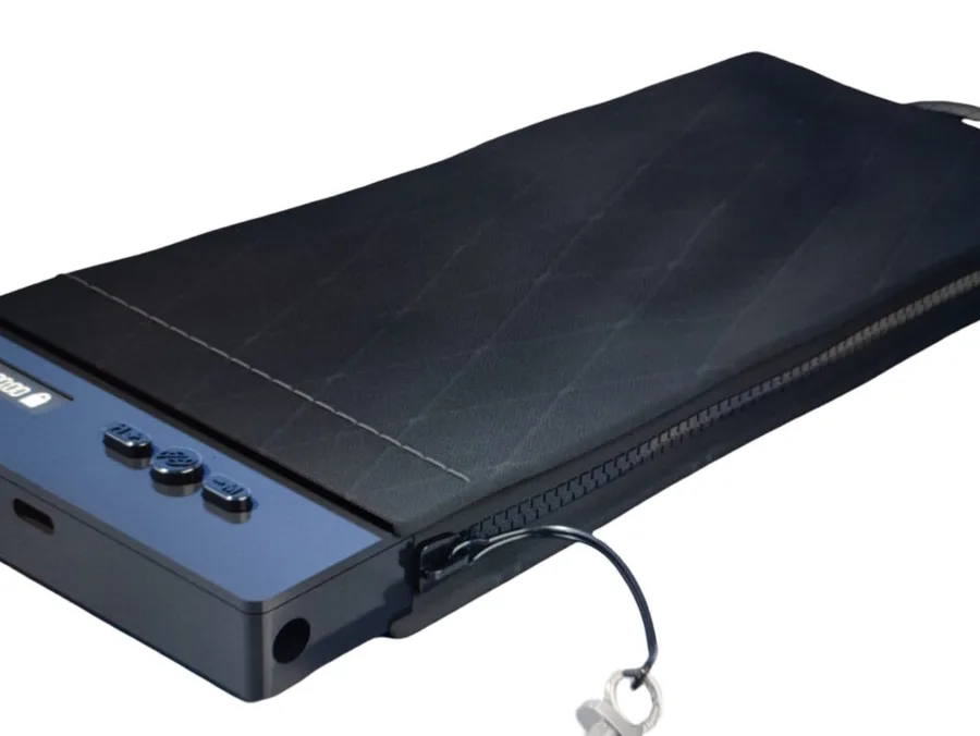
A mobile phone lock pouch we built to help users cut screen time needed a zipper that would not open until a countdown finished. That is a firmware problem wearing a mechanical costume. We designed and fabricated a custom PCB for the timer lock and developed the firmware that controls the locking logic, and the pouch’s form, a durable zip case with a smart electronic lock, only worked because the timing logic behind it was solid.
A LARP combat game system we designed shows the same thing from a different angle: RGB LEDs embedded in player armor change color based on health status, and a buzzer system fires sound alerts for game events like getting hit or losing health. None of that reads as complicated engineering from the outside, but it required PCB design tight enough to fit inside wearable shield geometry, with real-time responsiveness players would notice immediately if it lagged.
The clearest example: a scoring system built twice
Our Pickleball Scoring System case study is the sharpest version of this same story. It is a wall or net mounted device with PCB design, firmware, three mounting variants, and wireless sync to a wristband, built for a USA client who needed a device to survive outdoor courts for years, not months. The mechanical enclosure, the firmware, and the wireless sync all had to be engineered together from day one, because a scoring device that looks right but drops its wristband connection outdoors is not a shippable product.
That is the throughline across all of these: PCB Design, Firmware, and IoT are not separate line items you add to a mechanical project. On anything with a battery or a sensor, they are the project, and the enclosure gets built around them.