
Reverse-Engineering a Water Flosser: Inside a 15-Plus-Part Electromechanical Assembly
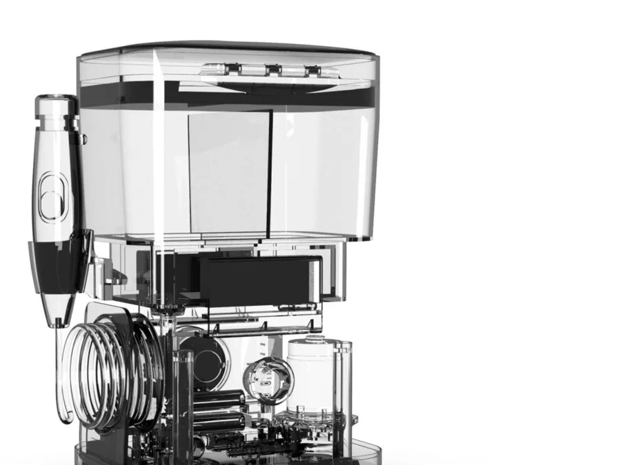
Not every product starts with a blank sheet. One of the more instructive projects we have worked on started with a client bringing us an existing, off-the-shelf water flosser and asking for something better: two specific features that were not commonly found on standard units, built into a design that still had to be manufacturable at scale.
Starting by taking it apart
Before we could design anything new, we reverse-engineered the existing water flosser to fully understand its working principles. That step is easy to skip when a deadline is tight, and it is also where most of the useful information about what to improve actually lives. Reverse engineering is not about copying a design; it is about finding exactly where a product’s constraints are, so the new work targets real problems instead of assumed ones.
Two features, two different engineering problems
The client wanted the ability to warm the water, for a more soothing clean, and a dual-liquid system that let a user run two different liquids, such as mouthwash and water, from the same compartment. Neither of those is a cosmetic feature. Warming water means a heating element that has to sit inside a housing full of moving fluid without becoming a safety or reliability risk. Dual-liquid handling means fluid pathways and a compartment design that has to keep two liquids properly separated and controllable, not just look like it does in a render.
Both features fed directly into the electronics. We designed the full electrical schematic and PCB layout, integrating the heating element and the fluid control system on the same board, so the housing design could not move forward until the board’s footprint, connector positions, and thermal behavior were locked.
Housing design that starts from the mold, not the sketch
Once the electronics architecture was settled, we built molding-ready housing files, designed from the start for injection molding and mass production rather than adapted to it afterward. That ordering avoids the common failure mode where a housing looks finished in CAD and then needs a redesign pass once someone checks it against real mold constraints, draft angles, wall thickness, parting lines.
A working proof-of-concept model validated the electronics, the heating element, and overall system performance before the design moved further, the same discipline we apply on every electronics-integrated product: prove the electronics work, then lock the geometry around them.
Where the 15-plus parts come from
The finished assembly design integrates more than 15 interlocking mechanical and electronic parts, seamlessly assembled around the PCB, the heating element, the fluid reservoir, and the dual-liquid mechanism. That number is not a design goal in itself; it is what happens honestly when a product has to warm water, route two liquids, house a PCB, and still assemble reliably on a production line. Getting an assembly of that complexity to go together the same way every time, at volume, is the actual test of whether the earlier reverse-engineering and DFM work was done properly.